
Features
Key Device Features
- 50-Channel GPS Receiver
- Network certified on multiple carriers
- Sprint (CDMA), Verizon (CDMA), AT&T (HSPA 3G)
- Internal or external antennae options
- Satellite can be added: Iridium
Fully Deployable Platform
- Plug & Play Deployment
- Device Communications: UDP, SMS
- Over-the-Air-Programming and Provisioning
(OTA) - Connect to sensor via Digital Input
- Customize device operation via scripting
Rugged & Reliable
- Industry Leading Warranty Options
- Field Installation and System Support
- J1455 Level 1 Pressure Wash
- FM Class 1, Div 2 Non-incendiary
- IP67
Robust Vehicle/Machine Interface Capabilities
- Interfaces to most light/med/heavy vehicles
- (1996 or later)
- Class I-VIII vehicles
- 12V & 24V power systems
- Customizable Interconnect Cables & Harnesses
- J-bus 6 pin, J-Bus 9 pin, Volvo 1962, Bobcat 7 pin,
OBDii, 3 wire
Installation is Simple
Installs into Any Powered Asset
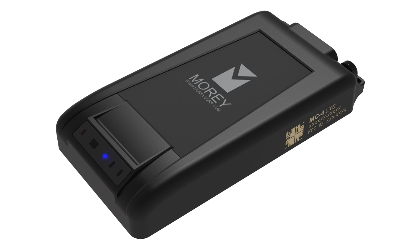
Temeda MC-4
For In-Cab & Under-Dash Applications
The MC-4 is ideal for powered assets with an operator cab and/or dashboard display. Utilizing the equipment’s integrated cellular and GPS antennas, the MC-4 provides reliable telematics solutions for single or mixed-vehicle fleets.
Recommended Install Types
- When to use a Power Bridge Harness? When the device needs to be connected to power and ground at all times. Ex. Asset has a Kill switch and the client prefers to bypass it, or if power is lost on a VBUS Harness when the Ignition turns off.
- NOTE: A Power Bridge Harness does not need to be installed with a 3 wire Harness due to the fact that it already has power and ground leads
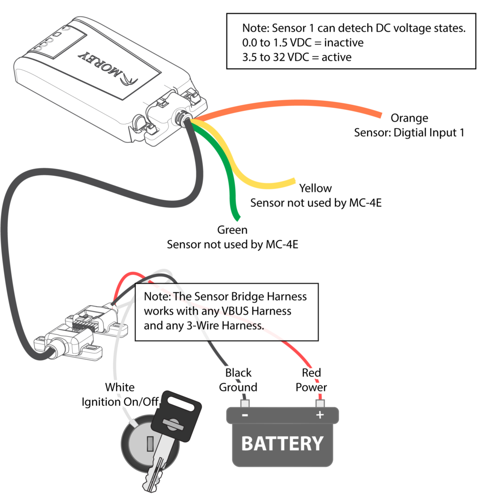
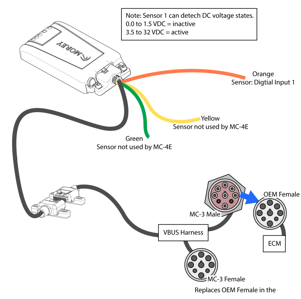
- When to use a Sensor Bridge Harness? When a client has requirements to detect digital inputs.
- Input range is 0-32VDC
- 1.5VDC = Low/Inactive
- 3.5-32VDC = High/Active
- When to use a Power Bridge and a Sensor Bridge Harness? When both scenarios above are needed when working with a VBUS Harness.
MC-4 Installation Guide
Configuration Diagrams
MC Power Bridge Harness and Vehicle BUS Harness Configuration

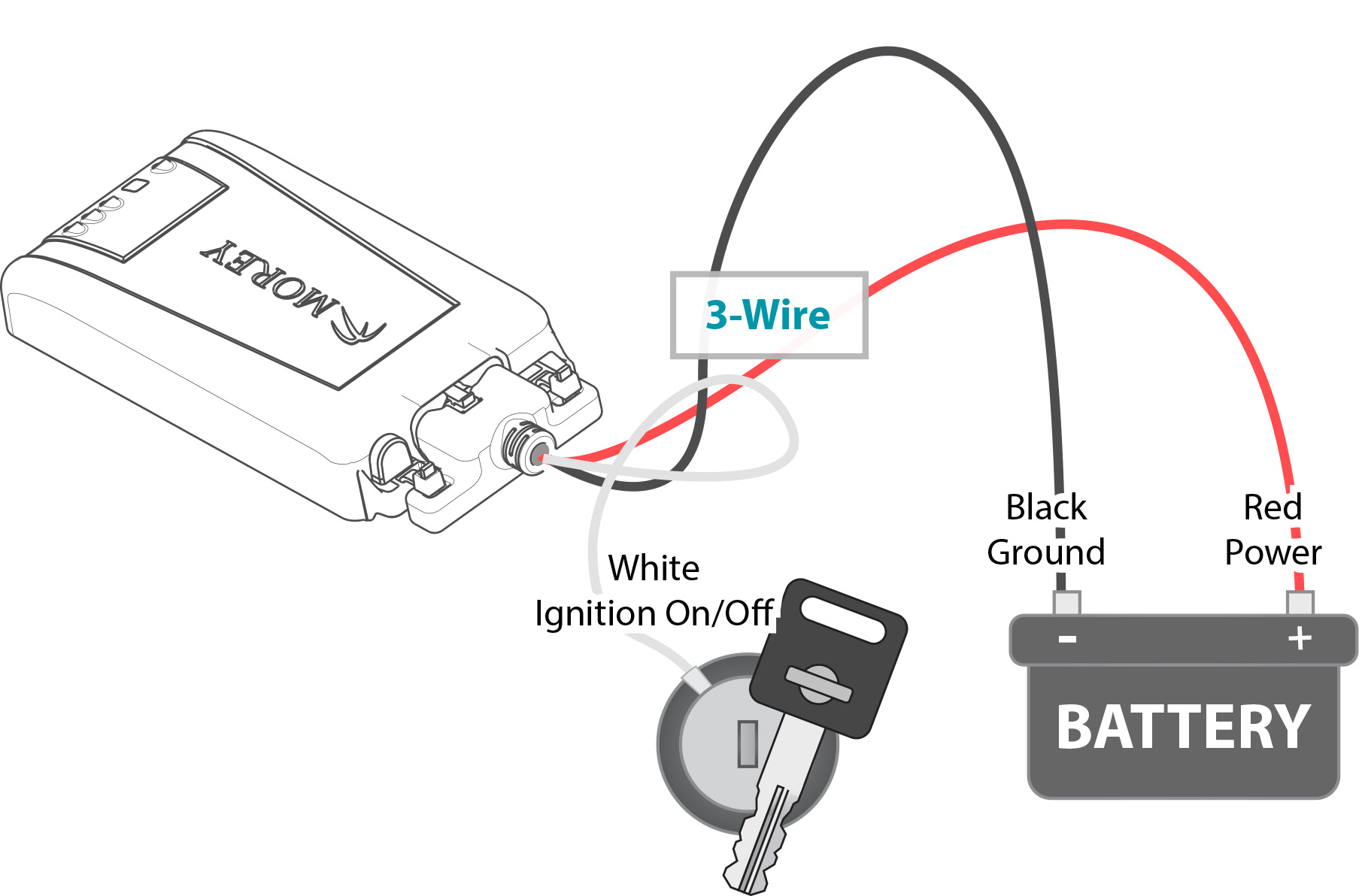
MC 3-Wire Configuration
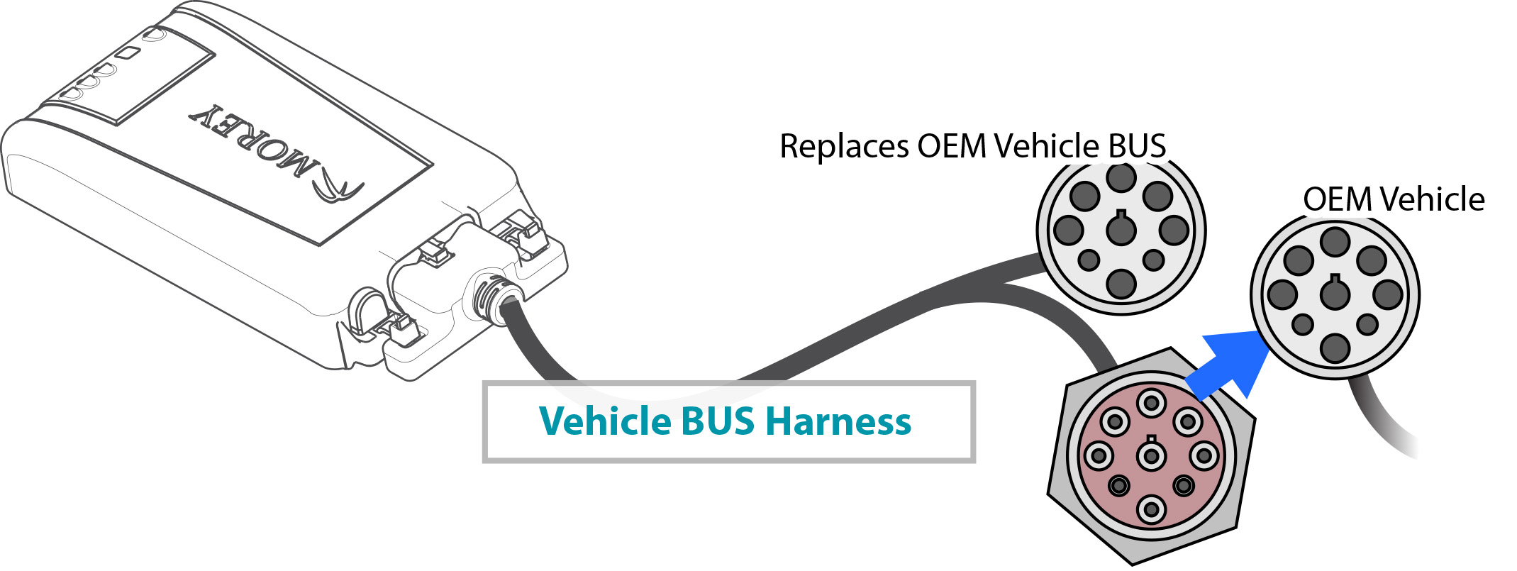
MC Vehicle BUS Harness Configuration
MC-4E Digital Input with 3-Wire Install Guide Drawings
MC-4E Digital Input with VBUS Install Guide
Just Finished Installing a GPS Device?
After a GPS Device is installed, someone should review the data being sent from the device to ensure the installation is complete. This step is vital to ensuring the accuracy of the information provided by the GPS device. Please review our Install Verification pages for more details.